- 您现在的位置:买卖IC网 > Sheet目录1889 > AD5174BRMZ-10-RL7 (Analog Devices Inc)IC DGTL POT 1024POS 10K 10MSOP
AD5174
Rev. B | Page 16 of 20
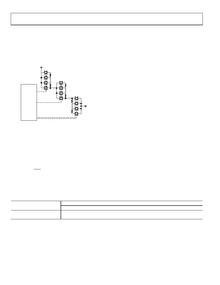
RDAC ARCHITECTURE
To achieve optimum performance, Analog Devices, Inc., has
patented the RDAC segmentation architecture for all the digital
potentiometers. In particular, the AD5174 employs a three-stage
segmentation approach as shown in Figure 27. The AD5174
wiper switch is designed with the transmission gate CMOS
topology.
A
W
10-BIT
ADDRESS
DECODER
RL
RM
RW
SW
RW
08
71
8-
00
7
Figure 27. Simplified RDAC Circuit
PROGRAMMING THE VARIABLE RESISTOR
Rheostat Operation
The nominal resistance between Terminal W and Terminal A,
RWA, is 10 kΩ and has 1024-tap points accessed by the wiper ter-
minal. The 10-bit data in the RDAC latch is decoded to select
one of the 1024 possible wiper settings. As a result, the general
equation for determining the digitally programmed output
resistance between the W terminal and the A terminal is
WA
R
D
R
×
=
1024
)
(
(1)
where:
D
is the decimal equivalent of the binary code loaded in the
10-bit RDAC register.
RWA
is the end-to-end resistance.
In the zero-scale condition, a finite total wiper resistance of
120 Ω is present. Regardless of which setting the part is oper-
ating in, take care to limit the current between Terminal A and
Terminal W to the maximum continuous current of ±6 mA or
a pulse current specified in Table 3. Otherwise, degradation or
possible destruction of the internal switch contact may occur.
Calculate the Actual End-to-End Resistance
The resistance tolerance is stored in the internal memory
during factory testing. The actual end-to-end resistance can,
therefore, be calculated (which is valuable for calibration,
tolerance matching, and precision applications).
The resistance tolerance (in percentage) is stored in fixed-point
format, using a 16-bit sign magnitude binary. The sign bit(0 =
negative and 1 = positive) and the integer part is located in
Address 0x39 as shown in Table 10. Address 0x3A contains the
fractional part as shown in Table 12.
That is, if the data readback from Address 0x39 is 0000001010 and
data from Address 0x3A is 0010110000, then the end-to-end
resistance can be calculated as follows.
For Memory Location 0x39,
DB[9:8]: XX = don’t care
DB[7]: 0 = negative
DB[6:0]: 0001010 = 10
For Memory Location 0x3A,
DB[9:8]: XX = don’t care
DB[7:0]: 10110000 = 176 × 28 = 0.6875
Therefore, tolerance = 10.6875% and RWA (1023)= 8.931 kΩ.
Table 12. End-to-End Resistance Tolerance Bytes
Data Byte1
Memory Map Address
DB9
DB8
DB7
DB6
DB5
DB4
DB3
DB2
DB1
DB0
0x39
X
Sign
26
25
24
23
22
21
20
0x3A
X
21
22
23
24
25
26
27
28
1 X is don’t care.
发布紧急采购,3分钟左右您将得到回复。
相关PDF资料
AD5175BRMZ-10-RL7
IC DGTL POT 1024POS 10K 10MSOP
AD5200BRMZ50-REEL7
IC POT DGTL 50K 256POS 10MSOP
AD5203ARZ100
IC POT DGTL QUAD 64POS 24SOIC
AD5204BRZ50
IC DGTL POT QUAD 50K 24-SOIC
AD5207BRU50
IC DGTL POT DUAL 256POS 14TSSOP
AD5220BNZ50
IC POT DGTL SGL 128POS 8DIP
AD5222BRUZ100
IC POT DGTL DUAL 128POS 14TSSOP
AD5227BUJZ10-R2
IC DGTL POT 10K UP/DN TSOT23-8
相关代理商/技术参数
AD5175
制造商:AD 制造商全称:Analog Devices 功能描述:Single-Channel, 1024-Position, Digital Rheostat with I2C Interface and 50-TP Memory
AD5175BCPZ-10-R2
制造商:AD 制造商全称:Analog Devices 功能描述:Single-Channel, 1024-Position, Digital Rheostat with I2C Interface and 50-TP Memory
AD5175BCPZ-10-RL7
功能描述:IC RHEOSTAT 5V 50-TP 1024 10MSOP RoHS:是 类别:集成电路 (IC) >> 数据采集 - 数字电位器 系列:- 标准包装:3,000 系列:DPP 接片:32 电阻(欧姆):10k 电路数:1 温度系数:标准值 300 ppm/°C 存储器类型:非易失 接口:3 线串行(芯片选择,递增,增/减) 电源电压:2.5 V ~ 6 V 工作温度:-40°C ~ 85°C 安装类型:表面贴装 封装/外壳:8-WFDFN 裸露焊盘 供应商设备封装:8-TDFN(2x3) 包装:带卷 (TR)
AD5175BRMZ-10
功能描述:IC DGTL POT 1024POS 10K 10MSOP RoHS:是 类别:集成电路 (IC) >> 数据采集 - 数字电位器 系列:- 标准包装:3,300 系列:WiperLock™ 接片:257 电阻(欧姆):100k 电路数:1 温度系数:标准值 150 ppm/°C 存储器类型:易失 接口:3 线 SPI(芯片选择) 电源电压:1.8 V ~ 5.5 V 工作温度:-40°C ~ 125°C 安装类型:表面贴装 封装/外壳:8-VDFN 裸露焊盘 供应商设备封装:8-DFN-EP(3x3) 包装:带卷 (TR)
AD5175BRMZ-10-RL7
功能描述:IC DGTL POT 1024POS 10K 10MSOP RoHS:是 类别:集成电路 (IC) >> 数据采集 - 数字电位器 系列:- 标准包装:3,000 系列:DPP 接片:32 电阻(欧姆):10k 电路数:1 温度系数:标准值 300 ppm/°C 存储器类型:非易失 接口:3 线串行(芯片选择,递增,增/减) 电源电压:2.5 V ~ 6 V 工作温度:-40°C ~ 85°C 安装类型:表面贴装 封装/外壳:8-WFDFN 裸露焊盘 供应商设备封装:8-TDFN(2x3) 包装:带卷 (TR)
AD5175JH
制造商:Analog Devices 功能描述:5175JH
AD517J
制造商:AD 制造商全称:Analog Devices 功能描述:Low Cost, Laser Trimmed, Precision IC Op Amp
AD517JH
制造商:Rochester Electronics LLC 功能描述:LOW IB, IOS, VOS OP AMP - Bulk